1965 Bsa 6 Volt Positive Ground Wiring Diagram
Half the volts 2 x the current. Click Here for Negative Ground Wiring Diagram.
 Inspirational Bosch 5 Pin Relay Wiring Diagram In 2020 Electrical Circuit Diagram Relay Diagram Design
On a 6 volt positive ground battery ignition the goes to the distibutor.
1965 bsa 6 volt positive ground wiring diagram. After World-War-II were positive ground and many stayed that way until the 1960s. Each part should be placed and linked to other parts in specific manner. Wiring diagram for 1940 Ford.
This is a collection of some wiring diagrams schematics for various motorcycles. Wiring diagram for 1946-48 Ford. If you have any Pre- 1960 Chevrolet Diagrams not listed here.
Refit the original pillar fixings removed in step 5. Diagram by Tim Dodge. This walk-thru is based on the original 8N tractor 6 volt wiring.
I have a podtronics 6 volt positive ground DC regulator. Wiring diagram for 1951 Ford. This is an Incomplete Collection of various schematics for Chevrolet Cars and Trucks.
Collection of three wire alternator wiring diagram. There are two ways to get enough Cubs. An exception to this was the 1955 Packard switching from 6v to 12v but not switching to negative ground.
Step 6 Figure 1 Snap in the DA plug and connect the red wire to the output side of the alternator 1032 stud take the long wire and connect to the side of the coil. Energy Transfer Ignition --- BSA-Triumph. This Diagram is NOT to be reproduced or used on any site without permission by Rask Cycle.
RASK CYCLE TECH TIPS. WIRING DIAGRAM FOR TRIUMPHBSA WITH BOYER IGNITION. BSA A65 the trigger may line up in a different position to that shown in figs.
All British vehicles imported to the US. Its components are shown by the pictorial to be easily identifiable. Most cars switched from 6 volt positive ground to 12 volt negative ground together.
Wiring See wiring diagrams on pages 6 7. Pazon Electronic Ignition Triumph BSA Norton Triumph 650cc Motorcycle Simplified Wiring Diagram VIDEO. The evolution of the less functional positive ground system is easily explained as before the invention of PVC-insulated plastic wiring in the 1960s live wires were covered with cloth insulation that performed poorly in the damp conditions found in the UK.
With 12 volt electrics positive or negative ground Features Fully digital design. Wiring diagram for 1937 Ford. So does that mean the pos.
May apply to others. Also make sure the cable from the battery to the starter is a 2 gauge or larger. Jaguar cars switched over in 1965.
WIRING DIAGRAMS FOR CHEVROLETS. BSA --- A75 1969-1970. Yes your 1946 John Deere A has a positive ground.
Yes note the ground cable Key 12 is connected to the positive terminal on the battery and the negative cable Key 1 goes to the starting motor. Go to the starter. These files are in Adobe Reader format pdf jpg Image Format.
Capacitor Ignition --- All. 4 on pages 10-11. Generator Internal Wiring Diagram - 6v Positive Ground 3-Brush by Wolfstone Thu Jul 11 2019 253 am in Farmall Cub.
Farmall H Wiring Diagram 1943 farmall h wiring diagram 1950 farmall h wiring diagram farmall h alternator wiring diagram Every electrical arrangement is composed of various different parts. Vintage 6 Volt Positive Ground Wiring Diagram Ford It is far more helpful as a reference guide if anyone wants to know about the homes electrical system. Wiring diagram for 1950 Ford.
Wiring diagram for 1949 Ford. If you are using a coil with external ballast resistor connect this wire to the battery side or key switch side of How To Wire Alternator 12-VOLT NEGATIVE GROUND 3 WIRE. Pazon Electronic Ignition for Triumph BSA Norton Twin 12v Motorcycles Pazon Ignitions.
A wiring diagram is a simplified traditional pictorial depiction of an electric circuit. 10 Connect the red wire from the transistor box to the positive terminal of the fi rst coil same point as the earth wire. Ensure that you have the correct version of the K-Tec 6 volt regulator depending on whether your motorcycle is negative or positive earth.
Make sure the cables and connections are in good shape including a good solid ground. I can do better tomorrow with a scanner if you need more detail. How to install a Pazon Electronic Ignition on your vintage Triumph Motorcycle.
Wiring diagram for 1942 Ford. Diagram of positive ground triumph wiring for boyer ignition. A bigger issue than the positive ground with the system is the 6 volts.
Take a look at the diagram below. Otherwise the structure wont work as it should be. Wiring diagram for 193839 Ford.
Wiring diagram for 1952-54 Ford 6 Wiring diagram for 1952-54 Ford 8. Some earlier 9N and 2N tractors had one-wire generators and used a cutout instead of a voltage regulator. The regulator must not be used without a battery as this may damage it.
See wiring diagram 11 Connect the white wire from the transistor box to the ignition switch feed on POSITIVE ground models and to a suitable earth on NEGATIVE ground models see wiring diagrams. May 03 Simple visual explanation of the wiring of the 6 volt Generator Regulator on My Farmall Super A 6 Volt Positive Ground. These Diagrams are easier to read once they are printed.
For some models eg. I was going to use it on my 55 BSA preunit but I decided to convert it to a 12 volt alternator system with a battery by Alton. Cable off the battery go to ground and the neg.
Click on the a link to open each one and click on the schematic to return. Wiring diagram for 1941 Ford. Last edited by Barnyard on Tue Jun 12 2012 303 am edited 1 time in total.
And other European nations. It shows the parts of the circuit as streamlined forms and also the power as well as signal links in between the gadgets. I did my best with my cell phone to snap you a few pics of the diagram that podtronics provides.
Is the least efficient diagram among the electrical wiring diagram. 2 809 by Glen. Quantity- Add to Cart HURRY.
The K-Tec 6 volt is a solid-state voltage regulator for motorcycles equipped with a Lucas 6 volt dynamo charging system.
 Triumph Spitfire Distributor Wiring Diagram Circuit Scott Wiring Diagram For Wiring Diagram Schematics
 Pin On Quad Bike Repairs
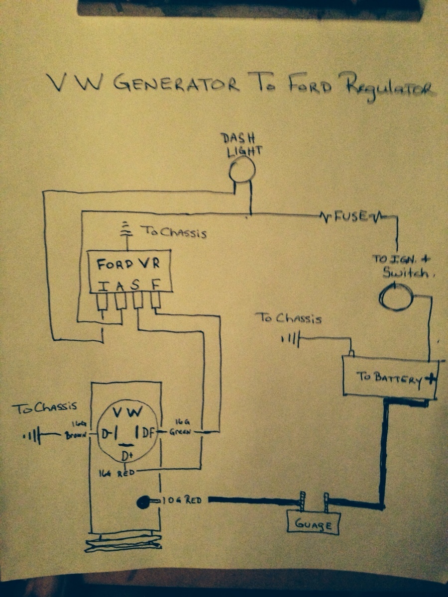
Vw Regulator Wiring Gfci Without Ground Wire Diagram Begeboy Wiring Diagram Source
 Image Result For Gy6 Cdi Wiring Diagram Electrical Circuit Diagram Electrical Diagram Electrical Wiring Diagram
 6 Volt Positive Ground Wiring Diagram Fuel Filter 2010 Maxima 7ways Yenpancane Jeanjaures37 Fr


