F40t12 Dimming Ballast Wiring Diagram
A Also applies to T10 lamps. It reveals the components of the circuit as streamlined shapes and also the power and also signal connections between the devices.
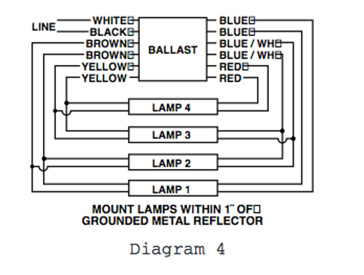
 Ge632max H90 S60 Ge 71497 Ultramax T8 Bi Level Dimming Ballast
A wiring diagram is a simplified standard photographic depiction of an electrical circuit.

F40t12 dimming ballast wiring diagram. For replacement of magnetic T12 electronic ballasts during maintenance or retrofits. Failure to meet the minimum value may cause a problem. The number of lamps.
Is the least efficient diagram among the electrical wiring diagram. I suspect the wiring is not as simple as described. Glass 17W 2100lm 4ft.
Replaced bulbs with known-good pair of same kind F40T12. 2 Philips Advance Ballast Quick Guide 3 Introduction 4 T8 ballasts 6 T5 ballasts 7 CFL ballasts 8 Magnetic T12 conversion to electronic 9 T12 ballasts 10 Dimming ballasts 11 Circline and signage ballasts 12 HID ballast kits 15 Grainger regional point of contact. Good light for 2 weeks then dark.
Variety of 2 lamp t12 ballast wiring diagram. SL15T Electronic Fluorescent 120V 12 F25T8 12 F32T8 F20T12 F25T12 F30T12 F34T12 F40T12 Ballast DISCLAIMER. The DOE ballast ruling effective April 1.
Sta nda rd a nd dimming. It shows the parts of the circuit as simplified shapes and the power and signal links between the devices. Emergency ballast and ac ballast must be fed from the same branch circuit lighted push button test switch lpbts ac emergency 1.
Wiring the Electronic T8 Ballast. Re-wiring diagrams can be requested for those who are replacing. 28 Dimming Ballast shall have a minimum ballast factor of 085 at maximum light output and 015 at minimum light output for primary lamp.
Example of Wiring a T8 Ballast. Refer to the following example which describes the basic conversion process. Prevents the sale of most.
2 InstantFit Ballast Compatibility Guide T8 instant-start ballasts See footnotes on Page 10. 7W 1050lm 2ft 9W 1200lm 3ft 10W 1600lm 4ft 13W 2100lm 4ft 14W 2100lm 4ft 14 W 2100 lm 4 ft. F40T12 2 40 5010 061 72 087 20 099 17 121 Wiring Diagram The wiring diagram that appears above is for the lamp type denoted by the asterisk.
Glass 165W 2500lm 4ft 13W 2100lm U-Bent3 469270 469288 469296 469304 469429 469445 469437 469320 469338 469346. F40T12 and F32T8 Rapid-Start Lamp-Ballast Compatibility Exceeding the maximum value may cause a problem. 2x - ft2427w f40t12 f25t8 cftr18w 2d28w ft18w f30t12 f17t8 f20t12.
We sell the latest and most up to date version of this product which comes with 6 lead wires. Consult the factory for other wiring diagrams. Its components are shown by the pictorial to be easily identifiable.
GE MVP T12 ballasts have the same wiring and mounting requirements as standard magnetic ballasts and provide up to 20 energy savings by simply replacing the ballast. All older models with 7 to 10 wires have been discontinued by Sunpark and are no longer available or manufactured. Wiring diagrams and more.
Two-wire phase-control dimming ballasts use existing line-voltage lines for both power and communication and are suitable for any application where greater flexibility is desired such as conference rooms boardrooms and private. F96T12 8 foot length. 315 V for starting capacitors rated at 004006 µf.
The lamps will be replaced with new T8 lamps as specified on the new T8 Ballast. NA Not applicable. Grounded shoplight fixture mounted in apartment kitchen had 2xF40T12 bulbs and noisy T12 ballast replaced with rapid-start electronic T12.
Ge F40t12 Ballast Wiring Diagram It is far more helpful as a reference guide if anyone wants to know about the homes electrical system. Philips Advance Ballast Quick Guide 3. The easy-to-understand model numbering system helps you choose and install the right model.
All older models with 7 to 10 wires have been discontinued by Sunpark and are no longer available or manufactured. They apparently forgot to draw the wiring diagram for the single tube setup though. Follow the colore-coded wiring diagram was the recommendation yet after connecting all like colors on the new ballast to the fixture all I got was a delayed dim light at the base of each fluorescent bulb.
The new ballast I purchased is designed for two tubes but states that it is also compatible with a single more powerful tube corresponding exactly to what I need. We sell the latest and most up to date version of this product which comes with 6 lead wires. Good light for 6 weeks then severe dimming.
Collection of lutron dimming ballast wiring diagram. The only diagram I have is for two tubes and seems to be typical. Tekonsha prodigy p2 wiring diagram full brake controller rf for envoy ke 90885 general electric trailer brakes thermostat wire Diagram Tekonsha Prodigy P2 Wiring Full Version Hd Quality Outletdiagram Radiotelegrafia It Prodigy P2 Brake Controller Wiring Diagram F40t12 Dimming Ballast For Schematics Diagram Tekonsha Prodigy P2 Wiring Full Version Hd Quality Outletdiagram Radiotelegrafia.
Some dimming ballasts are available that communicate with lighting controls using existing line-voltage wiring. SL15T Electronic Fluorescent 120V 12 F25T8 12 F32T8 F20T12 F25T12 F30T12 F34T12 F40T12 Ballast DISCLAIMER. A wiring diagram is a simplified traditional pictorial representation of an electric circuit.
F40T12 4 foot length. B For starting capacitors 008012 µf microfarads. 2 lamp t12 ballast wiring diagram f40t12 ballast wiring diagram wire center u2022 rh dododeli co Philips Ballast Diagram Rapid Start T12 Diagram 4 Wiring Bulbs Ballast.
So how to wire the new ballast to my fixture so it works.
Universal Dimming Electronic Fluorescent Ballast
 B340r277hp Universal Electronic Fluorescent Ballast F40t12 F30t12 Ballast
 Universal 256 472 800 T12 Magnetic Sign Ballast
 Allanson 696 At Magnetic Sign Ballast 30 To 48 Feet Total Length
 R 2s40 Tp Advance F40t12 Magnetic Ballast