Motorcycle Rectifier Wiring Diagram Shunt
In this video I show how to wire the rectifierregulator to the stator of the pitbike. Simply connect the 3 output wires from the 3 phase stator to the 3 yellow AC wires of your The Red and the Black - then connect into your motorcycle wiring.
 3 Phase Motorcycle Voltage Regulator Circuits Homemade Circuit Projects Voltage Regulator Circuit Projects Circuit
See diagram below regulator rectifiers you must use resisted spark plugs as circuitry is sensitive.

Motorcycle rectifier wiring diagram shunt. JAN 14 2020 - 17 MOTORCYCLE REGULATOR WIRING DIAGRAMMOTORCYCLE REGULATOR RECTIFIER WIRING DIAGRAM MOTORCYCLE. 5 pin regulator rectifiier wiring diagramSana makatulong po ito sainyo mga broPara sa iba pang vidio wag nyo pong kalimutan magSUBSCRIBELIKE AND SHARETO GOD. Building a regulator rectifier for motorcycle electronics forums 4 pin wiring diagram lamberts bikes msl 068 single phase revival cycles yamaha rock thanks pisolagomme it solid zone hoteloctavia understanding voltage homemade circuit projects old biker bert s british bike site 3 5 wire full version hd quality fuseboxdiagrams travexviaggi polaris 7 mercruiser starter hondaa accordd yenpancane.
The schematic is rather easy to understand. Is the least efficient diagram among the electrical wiring diagram. Huge buttons to navigate to Lamberts Bikes motorcycle regulator rectifier wiring diagrams.
I show how to make connections for the headlight. Its components are shown by the pictorial to be easily identifiable. I also show how to.
Download them direct to your device or view them online. Basic Preventive Maintenance Checks And Services ¾The rectifier enclosure should be maintained ¾Rectifiers must be allowed to cool properly ¾Rectifier enclosure must be properly grounded ¾Check all connections for tightness ¾All rectifier components should be kept clean. The 3 phase output from the alternator is sequentially applied across three power transistors which basically act like shunting devices for the alternator current.
Technical specifications after working on different voltage regulators i feel to share my findings on your blog so that other people may also get benefit. I was looking at your photos to make sure that I hook them up properly. The proposed 3 phase motorcycle voltage regulator circuit for motorcycle may be witnessed in the diagram below.
Typical Rectifier Wiring Diagram. Motorcycle regulator rectifier wiring diagram. Lamberts Bikes Motorcycle Part Wiring Diagrams Provided below is an online PDF document for Lamberts Bikes 2 phase 4 wire regulator rectifier wiring diagram.
Motorcycle Products RegulatorsRectifiers Ignition Unit TCI and CDI Systems Idling Stop ECUs Lighting Control Units Turn Signal Relays and LED Control Units Control Unit for Electric Motorcycle Power Drive Unit AC-AC. Weve included a whole. 2005 Pathfinder Radio Wiring Diagram It is far more helpful as a reference guide if anyone wants to know about the homes electrical system.
Regulator-Rectifier Wiring Diagramjpg 338KB View Image Jack I just received my regulators that I purchased from you. Regulator Rectifier Circuit Diagram Motorcycle and Motorcycle Mosfet Full Wave Shunt Regulator Circuit. The wiring diagram I have from a workshop manual shows only two coils probably for simplification and one of these is for the ignition system that I dont intend to modify in any way.
Like all good motorcycle engineers Lamberts Bikes have. 17 MOTORCYCLE REGULATOR WIRING DIAGRAM - MOTORCYCLE. Weve categorized all our regulator rectifier wiring diagrams into 2 phase and 3.
Regulator Rectifier Circuit Diagram Motorcycle and Ignition Alternator Kit For Bsa Triumph Norton Motorcycles. Motorcycle Regulator-Rectifier With Low Power Dissipation 2015-10-31 Author crutschow Creation date Oct 31 2015 Overview History Discussion This circuit is a design I worked on after three regulator failures Ive had on my. The coil in the diagram is shown attached at.
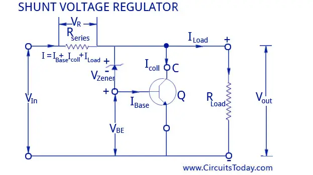
12v Three Phase Regulator Rectifier Fitting Instructions. In electronics a shunt is a device that creates a low-resistance path for electric current to allow it to pass around another point in the circuit1 The origin of the term is in the verb to shunt meaning to turn away or follow a different path.
 Voltage Regulators Circuits Types Working Principle Design Applications
 What Happens When Shunt Regulating A 3 Phase Stator All About Circuits
 Motorcycle Rectifier Wiring Diagram Shunt 2001 Honda Wiring Diagram 800sss Tukune Jeanjaures37 Fr
 3 Phase Voltage Regulator Series Type Techy At Day Blogger At Noon And A Hobbyist At Night
 3 Phase Regulated Ideal Rectifier Electrical Engineering Stack Exchange
